2D/3D Transformation, Viewing Transformation
Linear Transformations
Scale
\[\left[\begin{array}{l}x^{\prime} \\ y^{\prime}\end{array}\right]=\left[\begin{array}{ll}s_{x} & 0 \\ 0 & s_{y}\end{array}\right]\left[\begin{array}{l}x \\ y\end{array}\right]\]Reflection
\[\left[\begin{array}{l}x^{\prime} \\ y^{\prime}\end{array}\right]=\left[\begin{array}{cc}-1 & 0 \\ 0 & 1\end{array}\right]\left[\begin{array}{l}x \\ y\end{array}\right]\]Shear
\[\left[\begin{array}{l}x^{\prime} \\ y^{\prime}\end{array}\right]=\left[\begin{array}{ll}1 & a \\ 0 & 1\end{array}\right]\left[\begin{array}{l}x \\ y\end{array}\right]\]Rotation
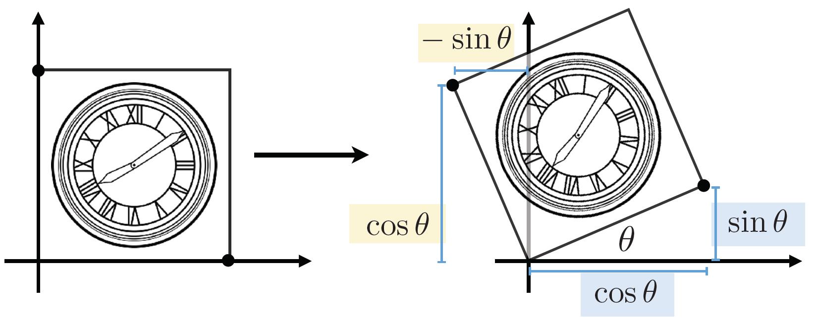
Tip: For the rotation matrix $M$, which is always normalized in orthogonal form. Thus the transposed matrix $M^{T}$ is exactly inversed matrix $M^{-1}$, that is: $M^{T}=M^{-1}$, where $M$ is orthogonal matrix
Linear Transformations
- Use the same dimension matrix
Affine Transformations
Homogeneous Coordinate
- Translation cannot be represented in matrix form
Hence, translation is Not linear transform
-
But we don’t want translation to be a special case, so is there a unified way to represent all transformations?
-
Add a third coordinate, and use 3D matrix to represent translations:
- 2D point $=(x, y, 1)^{\top}$
- 2D vector $=(x, y, 0)^{\top}$
- Valid operation if w-coordinate of result is 1 or 0
- vector + vector = vector
- point - point = vector
- point + vector = point
- point + point = ?
Info: In homogenous coordinates,
\(\left(\begin{array}{l}x \\ y \\ w\end{array}\right)\) is the 2D point \(\left(\begin{array}{c}x / w \\ y / w \\ 1\end{array}\right), w \neq 0\)
Thus, point + point = midpoint of two points
Affine Transformations
- Affine map = linear map + translation
- Using homogenous coordinates:
Note: This means linear transform first, and then translation.
Inverse Transform
$\mathbf{M}^{-1}$ is the inverse of transform $\mathbf{M}$ in both a matrix and geometric sense.
Composite transform
Composing Transforms
- Matrix multiplication is not commutative
- For a sequence of affine transforms $A_{1}, A_{2}, A_{3}, \ldots$
- Compose by matrix multiplication to speed up: \(A_{n}\left(\ldots A_{2}\left(A_{1}(\mathbf{x})\right)\right)=\mathbf{A}_{n} \cdots \mathbf{A}_{2} \cdot \mathbf{A}_{1} \cdot\left(\begin{array}{l}x \\ y \\ 1\end{array}\right)\)
- Pre-multiply n matrices to obtain a single matrix $\mathbf{A}_{n} \cdots \mathbf{A}_{2} \cdot \mathbf{A}_{1}$ representing combined transform
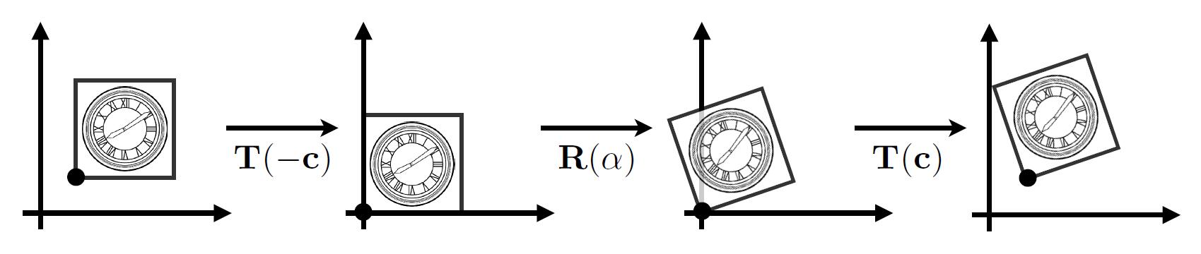
Decomposing Complex Transforms
How to rotate around a given point c?
- Translate center to origin
- Rotate
- Translate Back
3D transformations
Rotation around x, y, z-axis
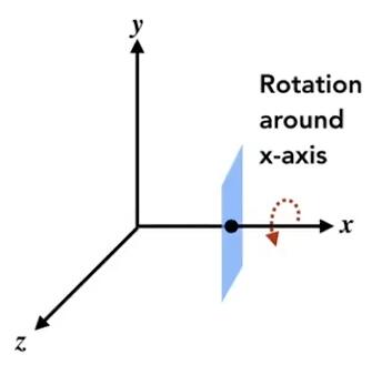
\(\mathbf{R}_{x}(\alpha)=\left(\begin{array}{cccc}1 & 0 & 0 & 0 \\ 0 & \cos \alpha & -\sin \alpha & 0 \\ 0 & \sin \alpha & \cos \alpha & 0 \\ 0 & 0 & 0 & 1\end{array}\right)\)
\(\mathbf{R}_{y}(\alpha)=\left(\begin{array}{cccc}\cos \alpha & 0 & \sin \alpha & 0 \\ 0 & 1 & 0 & 0 \\ -\sin \alpha & 0 & \cos \alpha & 0 \\ 0 & 0 & 0 & 1\end{array}\right)\)
\(\mathbf{R}_{z}(\alpha)=\left(\begin{array}{cccc}\cos \alpha & -\sin \alpha & 0 & 0 \\ \sin \alpha & \cos \alpha & 0 & 0 \\ 0 & 0 & 1 & 0 \\ 0 & 0 & 0 & 1\end{array}\right)\)
Caveat: In $\mathbf{R}_{y}$, where we use right-hand rule $z \times x$ get $y$, so the $\alpha$ is opposite.
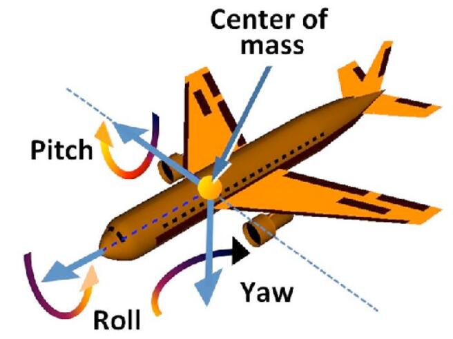
Euler angles
- To represent any 3D rotation from $\mathbf{R}_{x}, \mathbf{R}_{y}, \mathbf{R}_{z}$,
$\mathbf{R}_{x y z}(\alpha, \beta, \gamma)=\mathbf{R}_{x}(\alpha) \mathbf{R}_{y}(\beta) \mathbf{R}_{z}(\gamma)$
-
$(\alpha, \beta, \gamma)$ is Euler angles
-
Often used in flight simulator:
- Eluer angles may cause Gimbal lock: The loss of one degree of freedom.
- This suitation occurs when the axes of two of the three gimbals are driven into a parallel configuration as the below shows.
- Use Unit quaternions to solve this problem
Rodrigues’ Rotation Formula
- Rotation by angle $\alpha$ around axis $n$ (axis $n$ goes through the origin)
-
Formula derivation
-
If the rotation axis doesn’t go through the origin, but at $p$
- Translate the axis to origin. $T(-p)$
- Rotate. $R(n, \alpha)$
- Translate the axis back: $T(p)$
- Thus: $T(p)R(n, \alpha)T(-p)$
Viewing transformation
- View / Camera Transformation
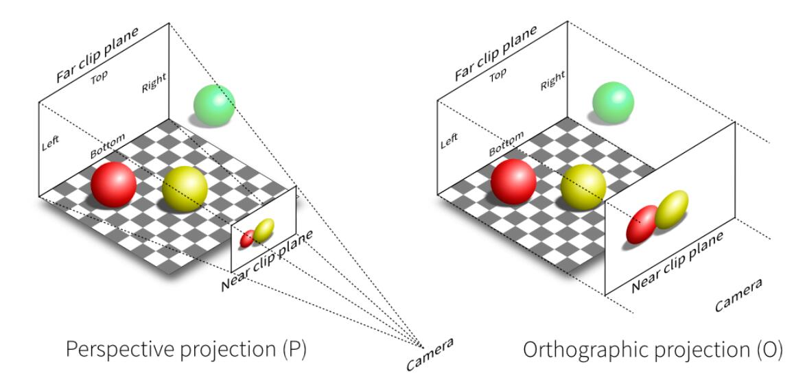
- Projection transformation
- Orthographics projection
- Perspective projection
A vivid analogy
- Analogous to taking a photo:
- Find a good place and arrage people (model transformation)
- Find a good “angle” to put the camera (view transformation)
- Cheese! (projection transformation)
View / Camera Transformation
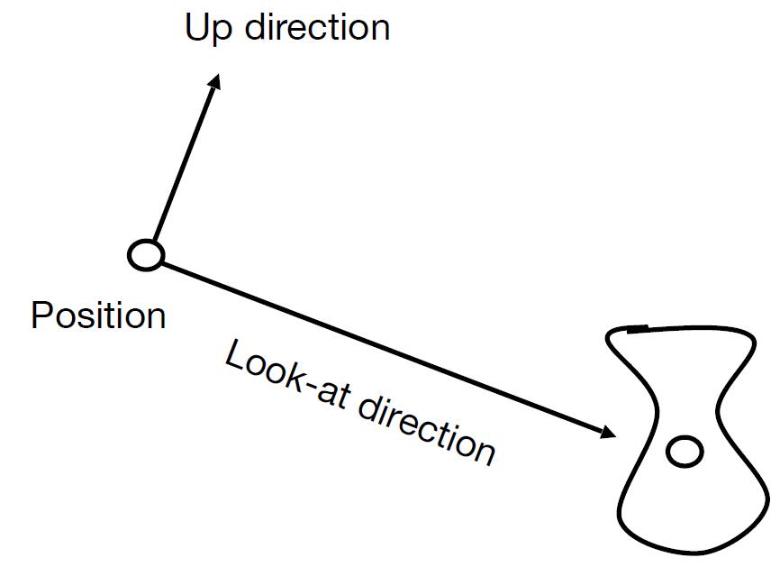
Define the camera
- Define the camera first (suppose every objects has been arranged properly)
- Position $\vec{e}$
- Look-at / gaze direction $\hat{g}$
- up direction $\hat{t}$
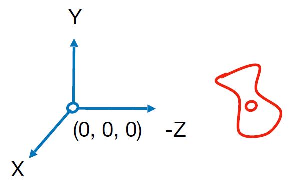
- Key observation: If the camera and all objects move together, the photo will be the same. Thus we transform the camera to the fixed origin point.
- Position: the origin
- Look-at direction: -Z
- up direction: Y
- Then transform the objects along with the fixed camera
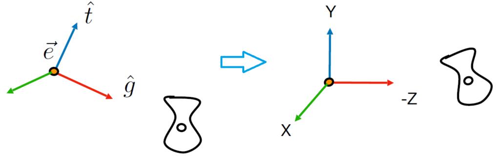
Transform the camera
- Transform the camera by $M_{\text {view}}$
- To locate it at the origin, up at $Y$, look at $Z$
- Translates $e$ to origin
- Rotates $t$ to $Y$
- Rotates $g$ to $-Z$
- If $t$ to $Y$ and $g$ to $-Z$, then $\hat{g} \times \hat{t}$ will be to $X$
- To locate it at the origin, up at $Y$, look at $Z$
- $M_{\text {view}}=R_{\text {view}}T_{\text {view}}$
- Translate $e$ to origin
\(T_{v i e w}=\left[\begin{array}{cccc}1 & 0 & 0 & -x_{e} \\ 0 & 1 & 0 & -y_{e} \\ 0 & 0 & 1 & -z_{e} \\ 0 & 0 & 0 & 1\end{array}\right]\) - Difficult to directly get $R_{view}$, so consider its inverse rotation:
\(R_{v i e w}^{-1}=\left[\begin{array}{cccc}x_{\hat{g} \times \hat{t}} & x_{t} & x_{-g} & 0 \\ y_{\hat{g} \times \hat{t}} & y_{t} & y_{-g} & 0 \\ z_{\hat{g} \times \hat{t}} & z_{t} & z_{-g} & 0 \\ 0 & 0 & 0 & 1\end{array}\right] \quad \Rightarrow \quad R_{v i e w} = (R_{v i e w}^{-1})^{T} = \left[\begin{array}{cccc}x_{\hat{g} \times \hat{t}} & y_{\hat{g} \times \hat{t}} & z_{\hat{g} \times \hat{t}} & 0 \\ x_{t} & y_{t} & z_{t} & 0 \\ x_{-g} & y_{-g} & z_{-g} & 0 \\ 0 & 0 & 0 & 1\end{array}\right]\)
- Translate $e$ to origin
Tip: We can validate the result of the multiplication of $R_{v i e w}^{-1}$ and the vector $\left(\begin{array}{llll}1 & 0 & 0 & 0\end{array}\right)$ which represents $X$ axis, the vector $\left(\begin{array}{llll}0 & 1 & 0 & 0\end{array}\right)$ which represents $Y$ axis, and the vector $\left(\begin{array}{llll}0 & 0 & 1 & 0\end{array}\right)$ which represents $Z$ axis. We could find $X$ axis rotates to $\hat{g} \times \hat{t}$, $Y$ rotates to $t$ and $Z$ rotates to $-g$.
Note: Each column of the $R_{view}$ except for the last column is the unit vector describing the camera, so the transposed matrix of it is its inversed matrix itself.
Projection transformation
Projection in Computer Graphics
- In orthogonal projection, the camera can be supposed to be placed infinite way from the viewing frustum (now the frustum becomes cuboid).
Orthographic Projection
- Camera located at origin, looking at -Z, up at Y
- Drop Z coordinate
- Translate and scale the resulting rectangle to $\left[-1, 1\right]^2$
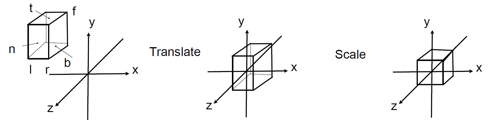
- More in general: map a cuboid $\left[l, r\right] \times \left[b, t\right] \times \left[f, n\right]$ to the canonical cube $\left[-1, 1\right]^3$. (left, right, bottom, top, far, near)
- Translate the center to origin first, then scale each edge to 2.
Note: Objects may be stretched out of the original scale, so the next viewport transform will deal with this and draw it back to the original scale.
Caveat: Looking along $-Z$ makes n > f (near > far) and this is the reason why OpenGL uses left hand coords.
Perspective Projection
- Most common in Computer Graphics, art, visual system
- Further objects are smaller
- Parallel lines not parallel, converge to single point
Note: We only consider Euclidean Geometry (Not Riemannian Geometry)
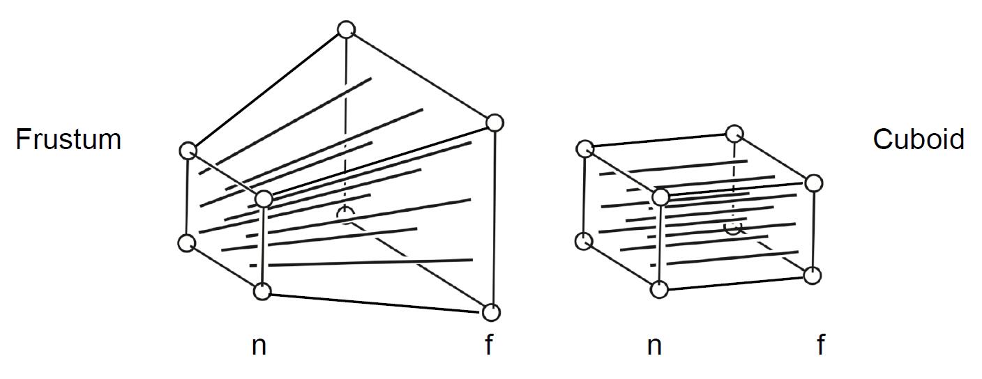
The step to do perspective projection
- First squish the frustum into a cuboid $M_{\text {persp} \rightarrow \text {ortho}}$
- Do orthographic projection $M_{ortho}$
- Denote vertical field-of-view (fovY) and aspect ratio (assume symmetry i.e. $l=-r\ b=-t$)
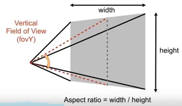
- Convert
fovYand aspect tol, r, b, t
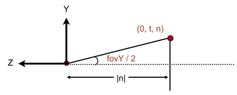
- Find the relationship between transformed points $\left(x^{\prime}, y^{\prime}, z^{\prime}\right)$ and original points $\left(x, y, z)\right)$
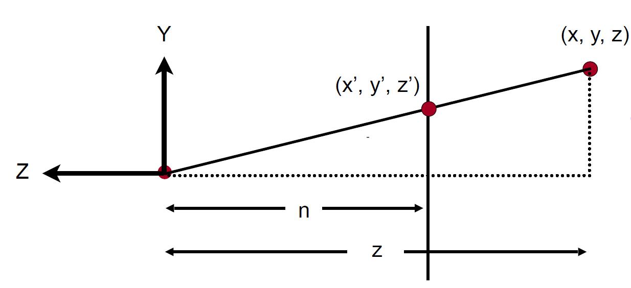
Similar to $x$:
\[x^{\prime}=\frac{n}{z} x\]- Use homogenous coordinates to represent this relationship:
Tip: according to the points defined in homogenous coordinates. reference
- So the operation squish should be the following form:
- Three known parameters could get a good reference of three rows of $M_{\text {persp} \rightarrow \text {ortho}}$:
- Two important observations, which is responsible for $z^{\prime}$:
1. Any point on the near plane will not change
\[M_{\text {persp} \rightarrow \text {ortho}}^{(4 \times 4)}\left(\begin{array}{l}x \\ y \\ z \\ 1\end{array}\right)=\left(\begin{array}{c}n x \\ n y \\ \text { unknown } \\ z\end{array}\right) \quad \begin{array}{l}\end{array}\]Replace $z$ with $n$:
\[\left(\begin{array}{l}x \\ y \\ n \\ 1\end{array}\right) \Rightarrow\left(\begin{array}{l}x \\ y \\ n \\ 1\end{array}\right)==\left(\begin{array}{c}n x \\ n y \\ n^{2} \\ n\end{array}\right)\]Thus, the third row must be of the form $(0\ 0\ A\ B)$:
\[\left(\begin{array}{llll}0 & 0 & A & B\end{array}\right)\left(\begin{array}{l}x \\ y \\ n \\ 1\end{array}\right)=n^{2}\] \[A n+B=n^{2}\]Tip: $n$ is only the known paramter, and has nothing to do with $z$, so $A$ and $B$ can not be determined yet.
2. Any $z$ of points on the far plane will not change
\[\left(\begin{array}{l}0 \\ 0 \\ f \\ 1\end{array}\right) \Rightarrow\left(\begin{array}{l}0 \\ 0 \\ f \\ 1\end{array}\right)==\left(\begin{array}{l}0 \\ 0 \\ f^{2} \\ f\end{array}\right)\] \[A f+B=f^{2}\]- From the two above equations we get, we could solve $A$ and $B$:
- Now, every entry of $M_{\text {persp} \rightarrow \text {ortho}}$ is known:
-
Finally, do orthographic projection $M_{ortho}$ to finish
-
In summary: $M_{\text {persp}}=M_{\text {ortho}} M_{\text {persp} \rightarrow \text {ortho}}$