Material, Microfacet Theory, Isotropic Material, Anisotropic Material
Material
- Recall that BRDF is used to calculate how much of the light ray will be reflected in a particular outgoing direction by the surface, which specify reflection ability and properties of the surface
- Material == BRDF
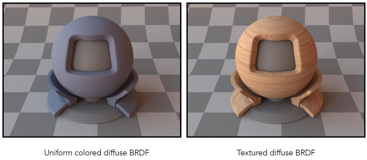
Diffuse / Lambertian Material
- Assume a senario with a reflected point
- Light coming in distributed uniformly in the hemisphere
- The point absorbs nothing energy and reflects all the energy out
- Light is equally reflected in each output direction
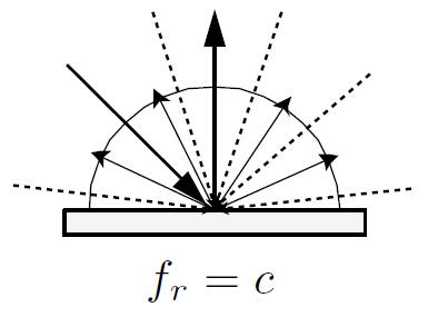
- On account of energy conservation, the energy absorbed and the enrgy emitted from the point is the same
- incident radiance equals to exitant radiance
- Denote reflection ratio $\rho$ (albedo) $0 \lt \rho \lt 1$
- Three dimensional vector to specify different ability of reflection regrading three colors
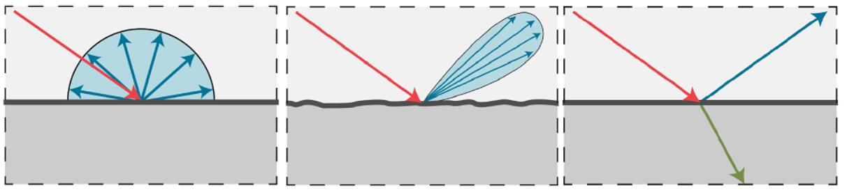
Material Category
Diffuse Material
Glossy Material
Ideal Reflective / Refractive Material
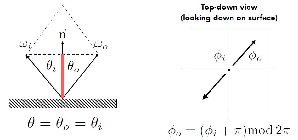
Specular Reflection
- Calculate zenith angle and azimuth angle
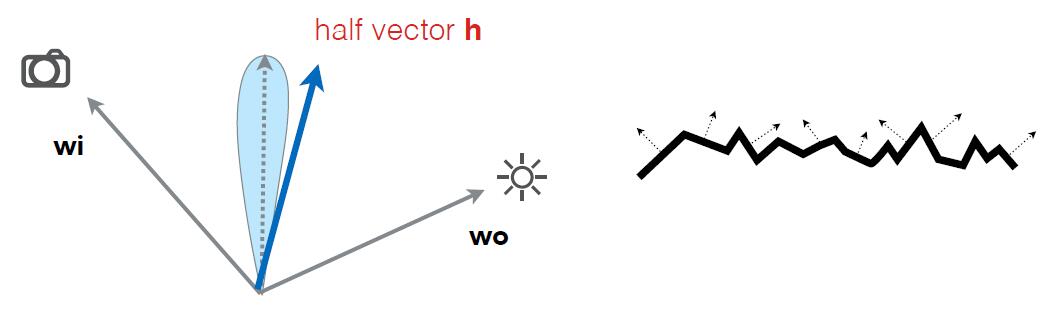
Tip: The difference between Blinn-Phong model and Phong model is the half vector, which is computed by adding incident vector and the vector of viewing direction. With dot product, Computing reflected is less efficient than half vector.
Info: BRDF distributes as Dirac δ function(distribution). The total area under BRDF curve is the albedo specifying what fraction of incident light is reflected in total, which is as opposed to being abosorbed or transmitted. For the perfect reflector, the area under the curbe sums to 1, because it reflects all of the incident light but in one direction. In this case, the δ function, with the area of 1, is an infinite thin and infinite tall spike at $x = 0$, which is ideal reflective material.
Note: Obviously, a real material can not be perfect specular reflector. First, the area under the curve is less than 1 due to some of the light absorbed. More importantly, the reflection peak can not be infinite thin so that the reflection will be blurred ever so slightly. This implicates that the peak will not be infinitely high. The wider the peak, the less hight it has to be to maintain the area of 1.
Specular Refraction
- In addition to reflecting off surface, light may be transmitted through surface.
- Light refracts when it enters a new medium.
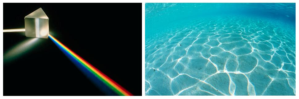
- Though the scattering of the light is due to the discrepancy of the wave length of light, we still consider it in geometric way as different refractive index in CG.
- The phenomenon of caustics as the right image shows is caused by light rays refracting off the uneven and curved surface of the sea and converging on the seafloor. It is tricky to deal with such thing in practical CG implementation.
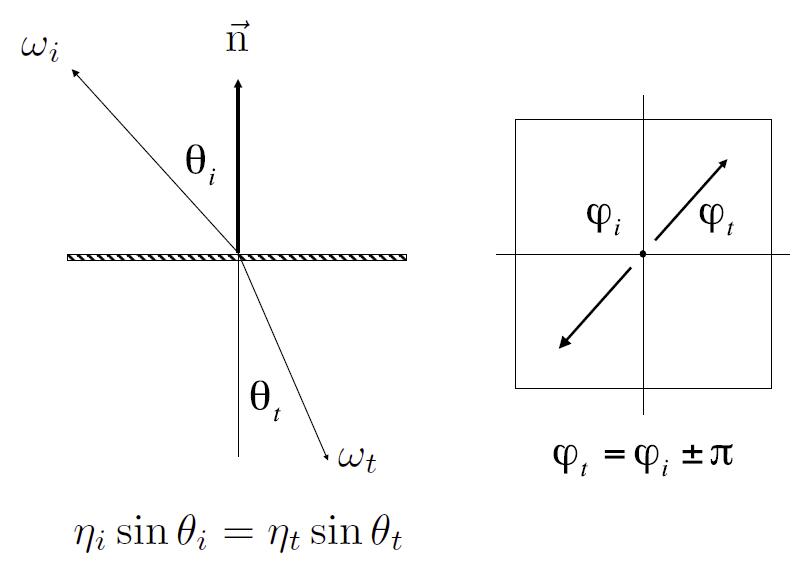
Snell’s Law
- Snell’s Law: Transmitted angle depends on
- index of refraction (IOR) for incident ray
- index of refraction (IOR) for exiting ray
- calculate azimuth angle in the same as reflection
| Medium | $\eta ^*$ |
|---|---|
| Vaccum | 1.0 |
| Air (sea level) | 1.00029 |
| Water(20°C) | 1.333 |
| Glass | 1.5-1.6 |
| Diamond | 2.42 |
-
index of refraction is wavelength dependent
-
Total internal reflection
- When light is moving from a more optically dense medium (e.g. water) to a less optically dense medium (e.g. air), which means $\eta_i / \eta_t \gt 1$
-
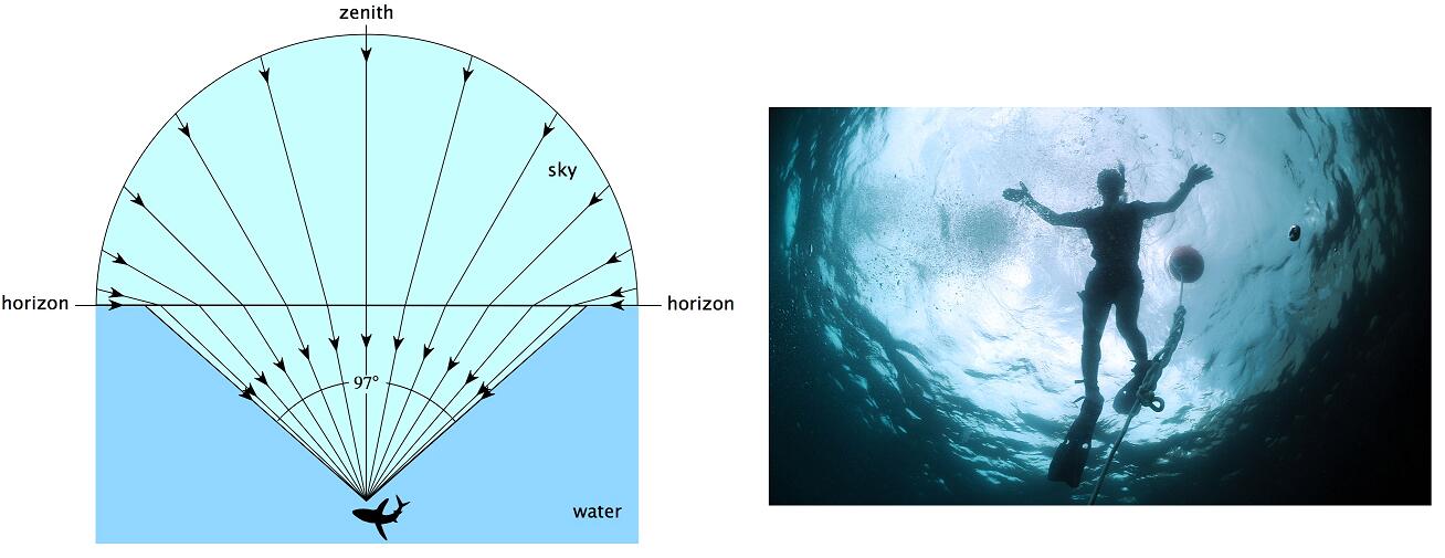
Light incident on boundary from large enough angle may not exit medium
- Snell’s Window / Circle: underwater viewer sees everthing above the surface through a cone of light.
- The area outside Snell’s window will be dark or show a reflection of underwater objects by total internal reflection
Tip: The sphere is symmetric object, which means that the light ray refracted into the sphere will always be refracted out.
info: BTDF (bidirectional transmittance distribution function) is similar to BRDF (bidirectional reflectance distribution function) but for the opposite side of the surface, especially used to evaluate how outgoing refractive light distributes at incident point. Further, BSDF (bidirectional scattering distribution function) is the generalization of BRDF and BTDF. Moreover, BSSRDF (bidirectional scattering-surface reflectance distribution function) describes the relationship between outgoing radiance and the incident flux, including the phenonmona like subsurface scattering.
Fresnel Reflection Term
-
Fresnel Reflection: predict the reflectance of smooth surfaces, and depends solely on the refractive index and the angle of incidence.
-
The inverted reflection in water gradually evanish with the increasing incident angle between the normal of horizontal plane and incident light.
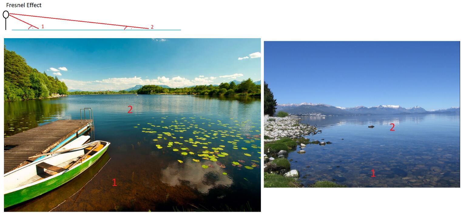
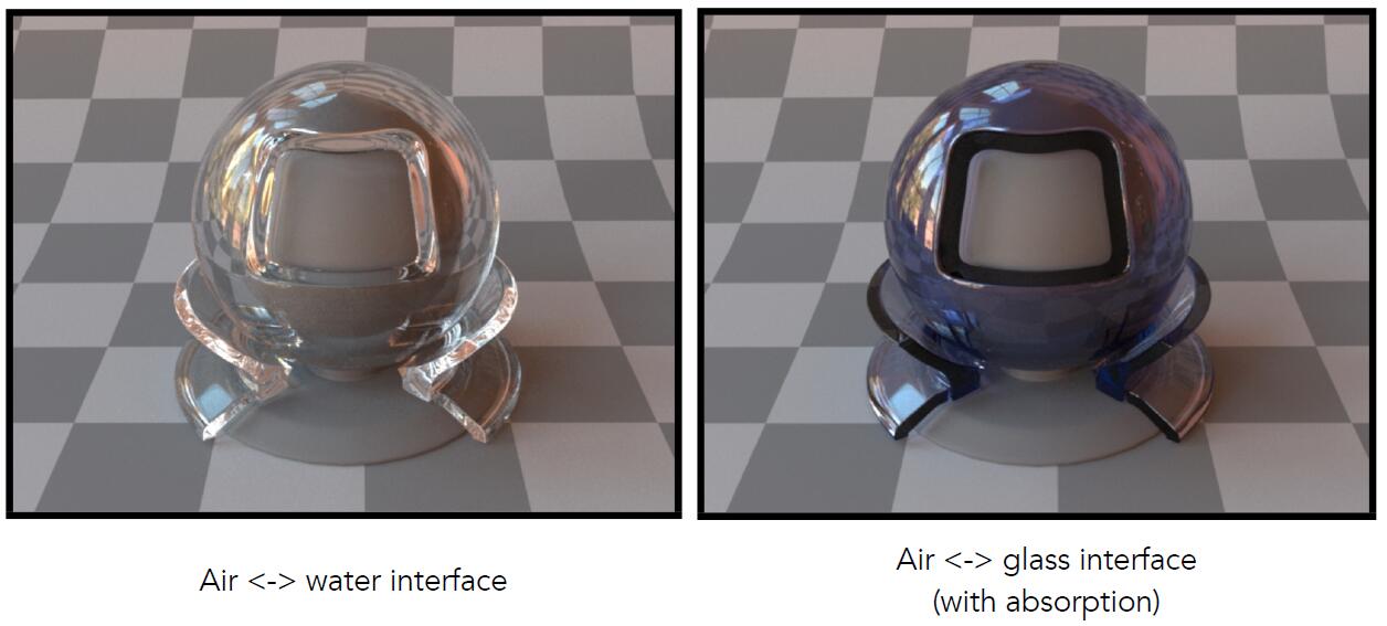
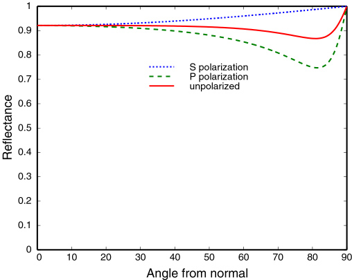
- Fresnel Term of Dielectric material ($\eta = 1.5$, i.e. most glasses and plastics)
- Reflectance increases greatly as the grazing angle increases
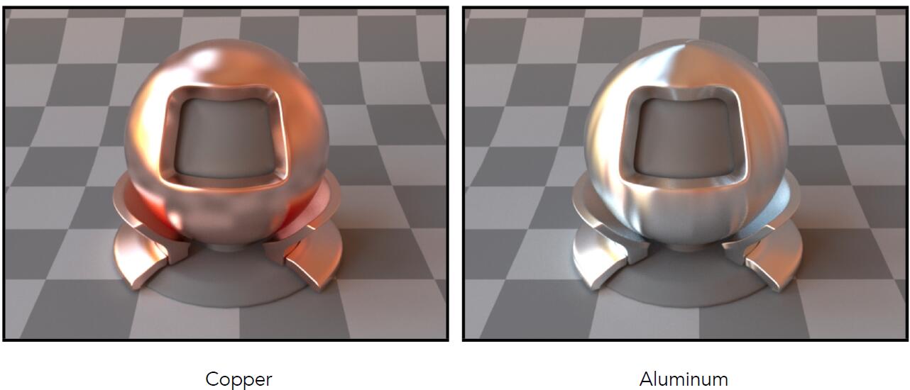
- Fresnel Term of Conductor (i.e. metals)
- The effect of Fresnel reflectance is subtle
Tip: Index of refraction of the conductor is actually the complex number, which contains two number $n,\ k$.
- This is the reason why people use polished metal (mercury) as mirror instead of polished glass.
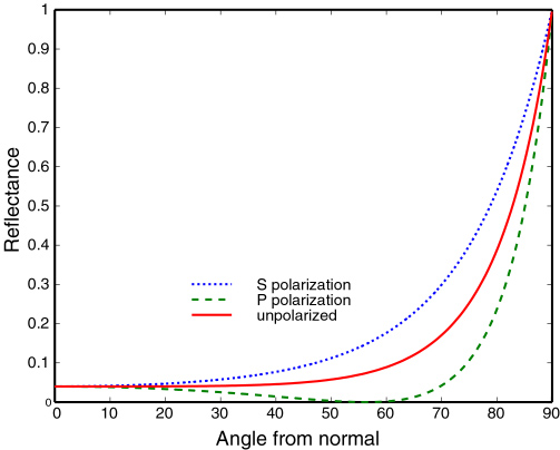
Info: Polarization is defined relative to the plane of incidence, i.e. the plane that contains the incoming and reflected rays as well as the normal to the sample surface. Perpendicular (s-)polarization is the polarization where the electric field is perpendicular to the plane of incidence. Parallel (p-)polarization is the polarization where the electric field is parallel to the plane of incidence.
Fresnel Equation
- Consider the light as a wave
- Accurate and need to consider polarization
- Effective reflectivity (unpolarized) is just the average of two reflectivities
Schlick’s approximation
- $\theta$ : angle between the incident light and the normal
- $n_1,\ n_2$ : indices of refraction of two media at the intrerface
- $R_0$ : reflection coefficient for light incoming parallel to the normal (the value of Fresnel term when $\theta = 0$)
Microfacet Material
Microfacet Theory
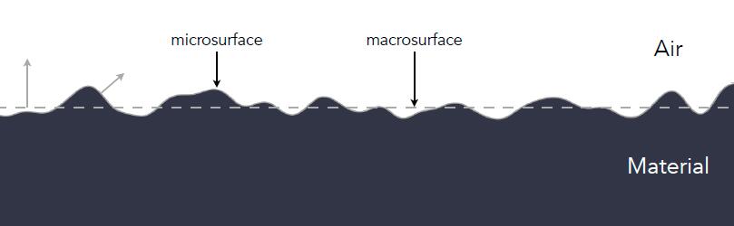
- Microfacet theory: Rough surfaces can be modeled as a collection of small microfacets
- Macroscale: flat & rough material, describe underlying smooth surface
- Microscale: bumpy & specular property, describe high variation of microfacet surfaces
- Individual elements of surface at like mirror
- Known as Microfacets
- Each microfacet has its own normal
- Intuitively, surface is regarded as material see from a distance, geometry see from closeup
- As the camera zooms out away from the surface, geometry will gradually fades into material.
Microfacet BRDF
-
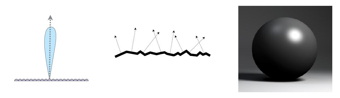
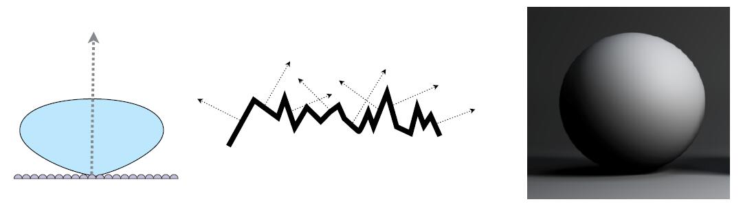
Microfacet BRDF: distribution of microfacets’ normals
- Concentrated <==> smooth <==> glossy
- Spread <==> rough <==> diffuse
- $f_{microfacet}$ : microfacet BRDF
- $F(i, h)$ : Fresnel reflectance term, the amount of energy reflected in terms of incident angle
- $G(i,o,h)$ : geometry term of shadowing masking between microfacet
- $D(h)$ : normal distribution term describing how microfacet normals is distributed around the given direction $h$
- $i$ : incident light direction
- $o$ : view direction
- $n$ : surface normal
- $h$ : half vector between $i$ and $o$
- More details discussed in paper Microfacet Models for Refraction through Rough Surfaces
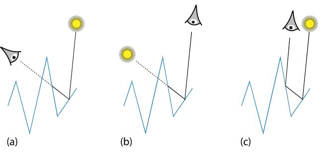
Info: Three Important Geometric Effects to Consider with Microfacet Reflection Models. (a) Masking: the microfacet of interest isn’t visible to the viewer due to occlusion by another microfacet. (b) Shadowing: analogously, light doesn’t reach the microfacet. (c) Interreflection: light bounces among the microfacets before reaching the viewer. Shadow-masking effect is obvious when the angle between incident light or viewing direction and normal is aounrd 90°, which we called grazing angle (掠射角).
- Microfacet model is widely used in PBR (Physically Based Rendering)
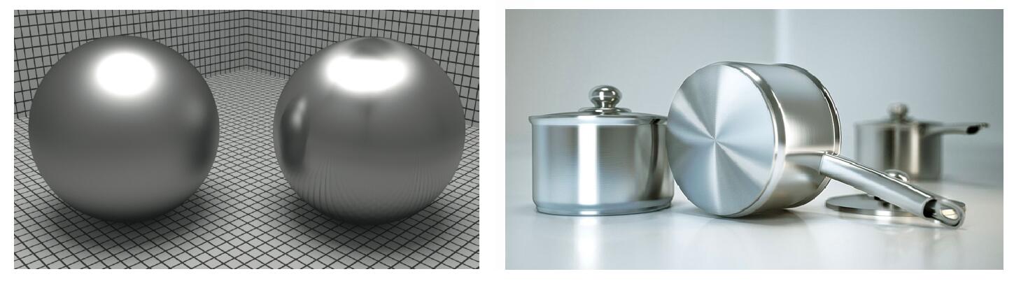
Isotropic / Anisotropic Material
- One way to classifying material: directionality of underlying surface
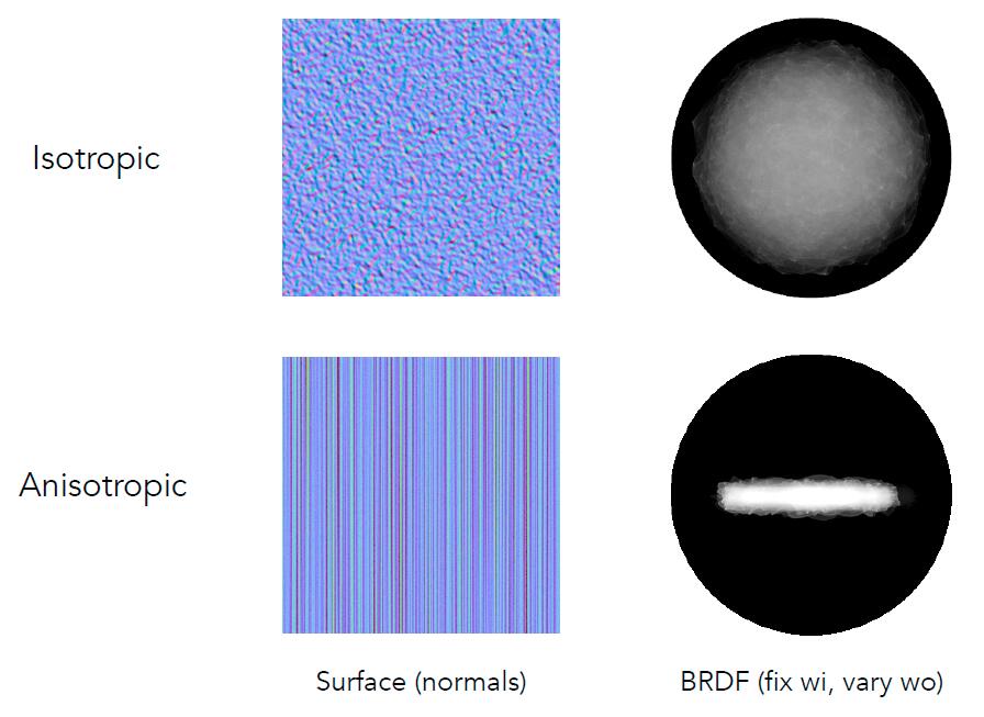
- Isotropic Material: have identical properties in all direction.
- Rotate around normal without changing reflections.
- BRDF only depends on relative location (azimuth angle) of the incident and exitent light ray
- e.g. Most materials
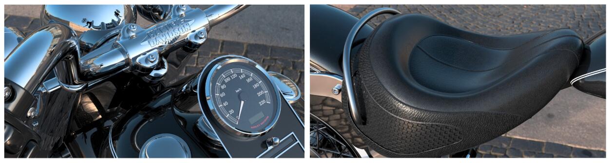
- Anisotropic Material: change properties with direction.
- Rotate on zaimuth angle $\Phi$ and change BRDF
- e.g. Brushed metal
- Some other anisotropic material
- Nylon: istropic along colum and row but not in the diagonal direction
- Velvet: self-defined microfacet material

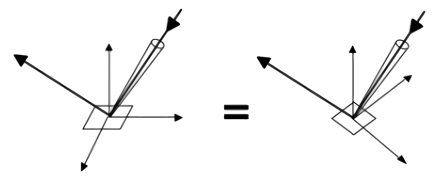
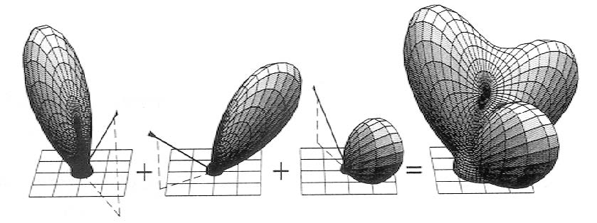
Properties of BRDF
- Non-negativity: BRDF represents the distribution of energy
- Linearity: In Blinn-Phong model, shading is the sum of ambient, diffuse, specular terms, while BRDF takes three parts as a whole.
- More generally, in many cases, material often require multiple ray tracing with different BRDF to achieve reflective properties.
- The total radiance of a point on a surface can be simply expressed as the sum of the radiance of multiple BRDFS.
- Reciprocity principle (可逆性): similar to the reciprocity of light ray
- Energy conservation: otherwise, the energy will not converge but explode in path tracing.
- Isotropic or anisotropic
- If isotropic:
- Then, from reciprocity:
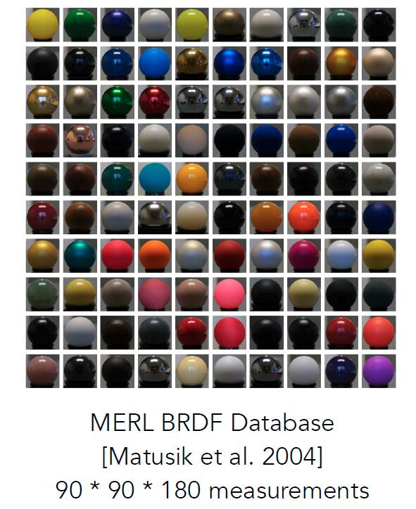
Measuring BRDF
Motivation of Measuring BRDF
- Avoid need to develop / derive models:the error of the theory model is sometimes very large
- Accurately render with real-world materials: automatically includes all of the scattering effects present and useful for product design, special effects, …
General Approach
- Image-based BRDF measurement: goniorreflectometer
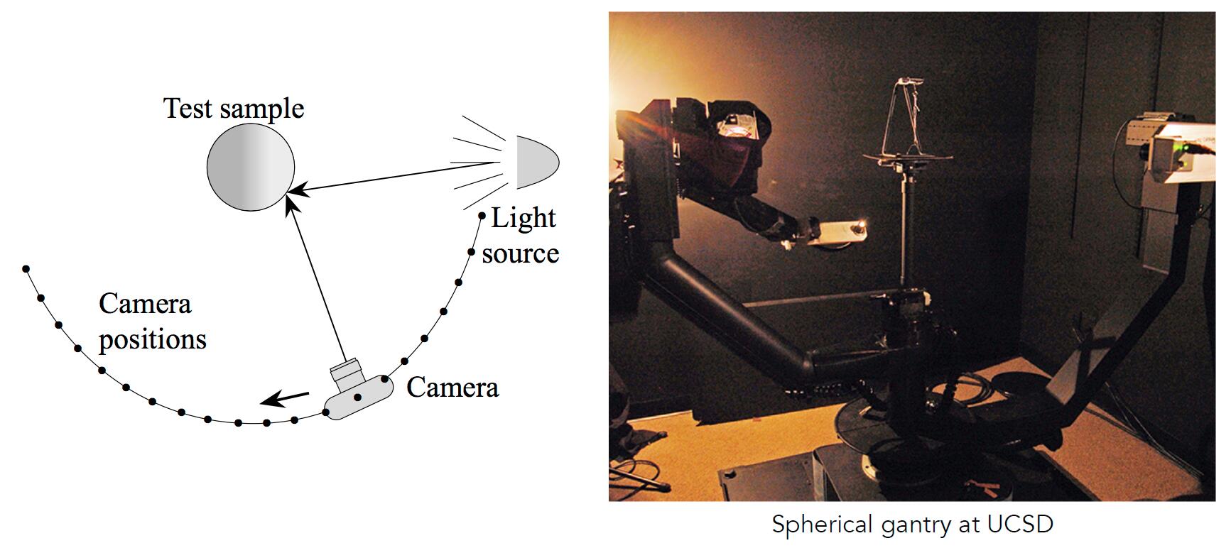
for outgoing direction w_o:
    move light to illuminate surface with a thin beam from w_o
    for each incoming direction w_i:
        move sensor to be at direction w_i from surface
        measure incident radiance
- Improving efficiency
- Isotropic surfaces reduce dimensionality from 4D to 3D
- 4D to 3D: $f_{r}\left(\theta_{i}, \phi_{i} ; \theta_{r}, \phi_{r}\right) \implies f_{r}\left(\theta_{i}, \theta_{r}, \phi_{r}-\phi_{i}\right)$
- Curse of dimensionality: with an increase dimension, the size of data surges
- Reciprocity reduces number of measurements by half
- Clever optical systems …
- Isotropic surfaces reduce dimensionality from 4D to 3D
Challenges in Measuring BRDF
- Accurate measurements at grazing angles
- Important due to Fresnel effects
- Measuring with dense enough sampling to capture high frequency specularities
- Retro-reflection
- Spatially-varying reflectance, …
Representing Measured BRDF
- Desirable qualities
- Compact representation
- Accurate representation of measured data
- Efficient evaluation for arbitrary pairs of diretions
- Good distributions available for importance sampling
- Tabular Representation
- Store regularly-spaced samples in $ ( \theta_i, \theta_o, \big| \phi_i - \phi_o \big| ) $
- Better: reparameterize angles to better match specularities
- Generally need to resample measured values to table
- Very high storage requirements
- Store regularly-spaced samples in $ ( \theta_i, \theta_o, \big| \phi_i - \phi_o \big| ) $